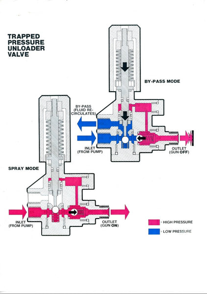
What is an unloader valve?4 Comments7 October 2019 | Ben Marriott A pressure washer unloader valve diverts the water flow through the bypass when the trigger on the gun is depressed. The Unloader valve is designed to respond to an increase in pressure or a change in water flow. The unloader valve can also be used for adjusting the pressure of your machine. The trigger on the gun and unloader valve together make up a two-part valve that directs water into the bypass of the unloader valve and then back in to the water inlet side of the pump or alternatively back to a header tank. The trigger shuts off the water flow, causing the unloader valve to re-circulate the water back to the header tank or into circulation within the pump head. This is sending the water into bypass. Trapped pressure unloaders go into bypass when the trigger is released causing an increase in pressure in the line. Flow-actuated unloaders divert water to bypass when there is a sufficient drop or stoppage of water flow through the outlet of the unloader. How a trapped Pressure Unloader WorksA trapped pressure unloader valve opens when there is an increase in pressure, so when the trigger on the gun is released (open) the pressure increases and opens the unloader valve sending the water back to a holding tank or back to the inlet side of the pump. A trapped pressure unloader is a simple valve with a spring mechanism mounted in a Brass or stainless steel body. There is a channel within the body that gives water access to the back of a piston. When the trigger is released the pressure against the piston increases and pushes the spring open to allow the water to pass into the bypass. If the trigger is pulled (closed), then all of the water will flow into bypass and back to the header tank.
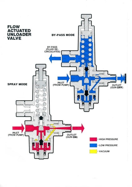
How a flow-actuated unloader worksThe flow-actuated unloader (the K series being the most common) responds to the water flow stopping, This will also create an increase in internal pressure. Whilst the pressure-actuated unloader has the check valve in the discharge port, which helps divert water to press the piston down and open the ball valve allowing water to bypass, the flow-actuated unloader has an orifice to perform the same function. When the trigger is released and the water flow stops, the system pressure is increased rapidly at all points in the system. The orifice allows the increased pressure to travel up the channel and in to the piston assembly, pushing the piston down. The rest of the water is sent through the bypass and back to the header tank or pump inlet. The biggest difference between this system and the pressure sensitive system is that when the trigger is released and the flow sensitive unloader valve is in bypass there is no trapped line pressure between the unloader and the trigger.
A pressure washer with a bypass sent back to pump inlet should not be run in bypass mode continuously. When a pressure washer is in bypass mode the temperature of the water in the closed loop increases rapidly due to the friction in the pump, which increases the temperature of the water. It is not good for the pump to handle water over 60 °C. Occasional discharge at the gun replaces water in the loop and prevents pump damage from high temperatures. Or having the bypass return to a holding tank where the pump is always getting a fresh supply of cold water. It is also a good idea to fit a thermal relief valve in this situation which opens when the temperature of the re-circulating water reaches 45°C. Using the Unloader Valve to Regulate Pressure: Trapped Pressure and flow-actuated unloader valves can both be used to control the pressure of a machine by adjusting the tension on the spring that holds the piston in the valve. Tightening the spring on a flow-actuated unloader reduces the pressure and on a trapped pressure unloader tightening the spring increases the pressure. When the adjustment bolt on a flow-actuated unloader is loosened, this causes the piston that controls the valve to rise, allowing more water through the gun and consequently a higher operating pressure. When the adjusting bolt on a trapped pressure unloader is loosened, the tension on the spring is reduced and therefore causes the piston assembly tension to lessen meaning that it can open into bypass at lower pressures, allowing less water to be forced out of the gun and as a result a lower operating pressure. In the case of trapped pressure unloader valves it is of the utmost importance that the limiting nuts should be set correctly to allow the unloader to bypass at the correct pressure without damaging the unit. Adjusting a trapped pressure unloader valve Trapped pressure unloaders must always be adjusted with the pressure washer operating and the trigger pressed so the water is flowing through the gun. The initial adjusting position should be loose or screwed away from the body and with little tension on the spring. Release the trigger to see if the unloader is working. Press the trigger, and allow the system to develop its operating pressure at that adjustment. Take note of the pressure gauge reading. Press the trigger and tighten the adjusting bolt. Repeat until the desired pressure is achieved. Use the gauge to monitor the systems pressure rise with each adjustment. All adjustments must be made with water flowing and pressure in the system. Release the trigger to check spike pressure. This adjustment procedure is exactly the opposite of the procedure for adjusting the flow actuated unloader. Adjusting a Flow Sensitive Unloader Valve (The following example is for a K1 Unloader) Flow sensitive unloader valves are set by adjusting the unloader bolt and securing nut. Choose the correct size nozzle for the unit which permits a 5% of the total unit flow to be in continuous bypass whilst allowing the unit to operate at a constant pressure. Prior to set-up set the unloader valve to its lowest setting by turning the adjustment bolt clockwise until it hits the stop. Follow the pressure washer unit's guide for start up. Once running cycle the unloader valve to ensure the system is primed fully. With the trigger pulled, gradually increase the pressure by turning the adjustment bolt anti-clockwise in increments of 200 PSI cycling the unloader after each adjustment repeating the sequence until the desired operating pressure is reached. Once this operation is complete set the locking nut, shutdown the machine and restart to confirm that the correct pressure has been set.
|
|